Here you can find the potential analysis of a semi-active anti-roll bar based on MR technology. Presented by Tobias Tarne at the chassis.tech plus 2024.
The trend towards larger vehicles, particularly SUVs, is continuing, leading to higher and, in conjunction with electromobility, heavier vehicles. This results in an increased tendency to roll and pitch, causing increased movement of the occupant’s head and upper body when changing direction, which can be uncomfortable and cause nausea. Although a rigid/hard stabilizer bar can help, it significantly reduces ride comfort when driving over one-sided bumps. Fully active suspension systems (e.g. Active Ride) solve this conflict, but are expensive and technically complex. According to our information, active electro-mechanical roll stabilizers from German suppliers are only available to a limited extent and are also technically demanding. Purely mechanical roll stabilizers have too small an operating range and, due to fixed mechanical pre-settings, cannot adapt quickly enough to different situations, such as a sudden sharp turn.
There is therefore a significant technical gap between a fully active suspension and a simple stabilizer bar, especially for cost-sensitive mid-range vehicles and vehicles with limited installation space.
The solution:
Our Adaptive Roll Stabilizer fills this gap as it is compact, adaptive in real time (through software specifications) and cost effective to manufacture. Modern vehicles are software-defined and can therefore make the most of actuators that are continuously controlled by software – such as our INVENTUS adaptive stabilizer.
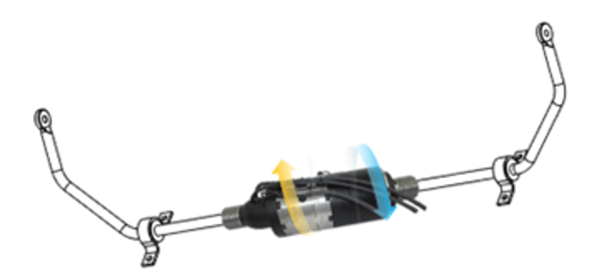
After suspension and damping, stabilizers are the third basic chassis component that determines handling characteristics. Usually designed as elastic torsion bars, they connect the wheel carriers of an axle and limit the lateral inclination of the vehicle when cornering. By adjusting the stiffness of the stabilizer bars on the front and rear axle, it is possible to influence the wheel load distribution during cornering and thus the self-steering behavior. Stabilizers influence the suspension behavior, especially when driving over bumps on one side of the road, because they transfer the forces to the other side. The setup is therefore always a compromise between the lowest possible lateral inclination and good suspension comfort with reciprocal suspension. In contrast to passive suspension bars, semi-active or active roll stabilization can resolve this trade-off. The self-steering behavior can also be actively influenced.
The MR anti roll bar automatically adapts to changing driving conditions and ensures maximum stability and comfort. Whether for fast cornering or on uneven roads, the MR stabilizer offers a tailor-made solution for all road conditions.
Efficiency
The MR anti roll bar’s adaptive technology not only improves comfort and driving dynamics, but also optimizes the efficiency of your vehicle, as only a small amount of energy is required for locking.
Safety and comfort
The system ensures greater driving safety by damping unwanted movements of the vehicle. At the same time, the MR anti roll bar offers unparalleled ride comfort for a relaxed driving experience.
Technology
The MR anti roll bar embodies the best in innovation and technology and . Be at the forefront of progress and benefit from the latest developments in adaptive stabilization systems.
The parts that pivot towards each other (rotor to housing) are sealed magnetically (magnetic field plus MR medium); no sealing lips in the usual sense are required. This is an important difference/advantage of the magnetorheological pivoting vane compared to the state of the art with oil and valves, particularly in terms of tightness and service life. It also reduces manufacturing costs.
Realized systems:
Automotive
Adaptive roll-bar
Health Care
Prosthetics
Application requirements / advantages
Semi-active system for SUVs
Left to right decouplable – this allows larger wheel interlocks
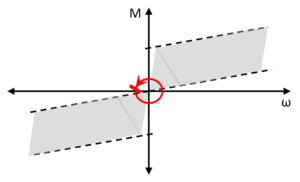
Operating principle: Rotary vane or pivoting vane

The magnetic field acting radial to the flow gap causes the iron particles to be aligned in the direction of these magnetic field lines.
This linking of the iron particles generates an increased shear stress in the area of the flow gap (neon green) and ultimately an increased pressure drop.
The level of the generated shear stress/height of the magnetic field and thus the level of the pressure drop/torque can be set as required based on the applied current.
A permanent magnet can be used as a fail-safe device, which provides a defined/constant magnetic field and thus torque for the actuator in de-energized operation. The magnetic field strength of the permanent magnet can then be amplified or attenuated in driving mode/control mode using the solenoid coil.
Variably adjustable damping force via the MR effect
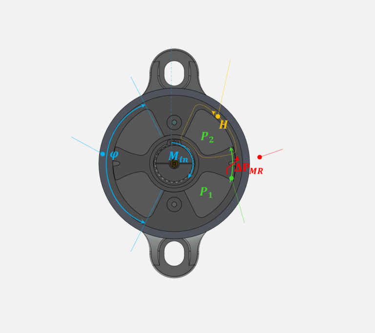
In „off-state„, the mode of operation corresponds to a conventional hydraulic system with a speed-dependent base curve. The damping force results from the pressure drop:
𝐹_𝑑 = 𝑓(𝑃_1 − 𝑃_2 )
In „on-state„, the pressure drop is influenced by an additional pressure drop generated by the magnetic field. The damping force corresponds to:
𝐹_𝑑 = 𝑓(𝑃_1 − 𝑃_2 + Δ𝑃_𝑀𝑅)
Magnetic path – field lines across the effective gap
Swivel angle
Effective gap – flow channel for MR fluid
Adjustable damping force
Adaptive anti-roll bar
Requirements at the start of the project:
Maximum torque and power requirement (hard position): 1200 Nm at 60 watts (vehicle)
Outside Diameter: 91 mm (as with the active solution from Schäffler)
Operating angle: 20°
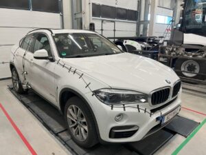
Vehicle: BMW X6 Type: F16 Year 2018
System for front and rear axle Stabiliser diameter: Front D26 mm – Rear D 19.2 mm
Stand-alone solution preferred for prototypes (later communication via CAN bus possible)
After completing the test measurements, it was determined that such high locking torques are not necessary with the spring rate used for these stabilizer halves. A maximum locking torque of 600 – 800 Nm would be sufficient for the front axle. The torques required on the rear axle are considerably lower.
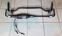
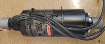
Assembled and implemented
MRF and gear unit assembled (1200 Nm)
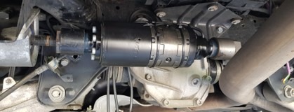
Device integrated into the vehicle
Vehicle with device
In action
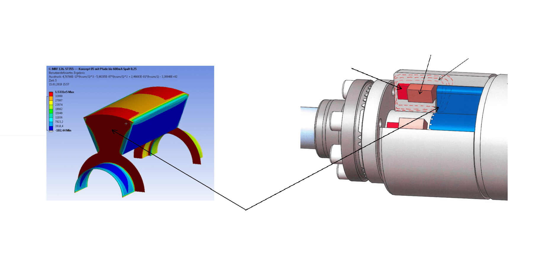
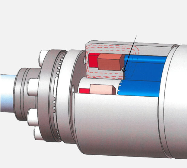
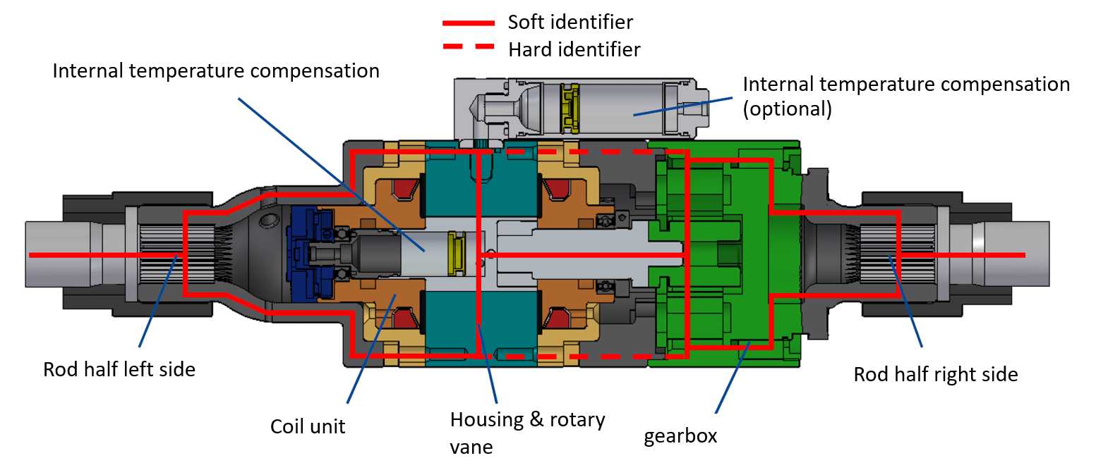
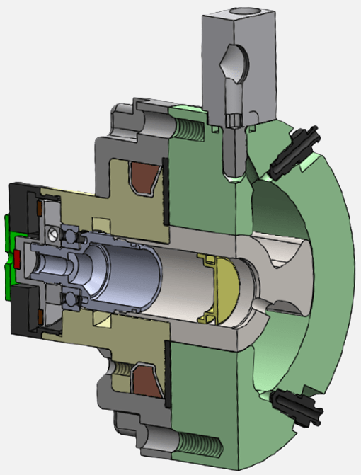
Internal sealing concept
The moving parts (rotor to housing) of the pivoting vane are magnetically sealed, so no sealing lips are required. This is an important difference/advantage of the magnetorheological pivoting vane compared to the state of the art with oil, particularly in terms of tightness and service life. It also reduces manufacturing costs (lower requirements for tolerances, surface roughness and surface hardness).
Magnetic flux
Solenoid coil
Permanent magnet (fail-save)
Axially sealing magnetic field
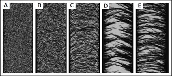
Sealing with MR fluid
Sealing using MR fluid is possible due to the chain formation, as shown in the following image. There must be a small gap between the moving parts where the MRF is located. All gaps are exposed to a magnetic field so that they seal the gap in conjunction with the carbonyl iron particles (the particles chain together magnetically in the gap). The „sealing effect“ and the resulting pressure vary depending on the strength of the magnetic field.
The rotating shaft is sealed with two conventional radial seals. The MR fluid thus remains in the system and is protected from environmental influences (water, dust, dirt, etc.).
Sealing gap MR-Fluid
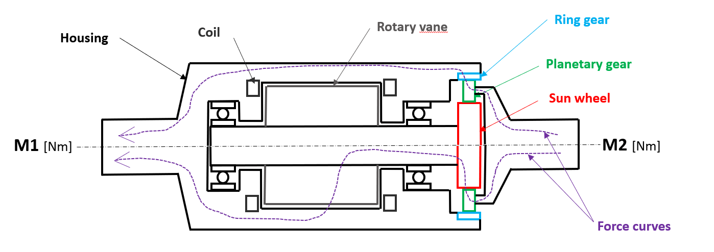
Force curve with planetary gearbox
Locking situations:
As long as the housing is not held by the body in any way (rigid or deformable), the following always occurs M2 = -M1 (actio = reactio)
Rotary vane locks 100%: Attention!!! Mechanical torsion due to the load in the rotary vane is translated 1/i times.
Characteristic data ATD 1200
Dimensions ∅ 91 x 193/204 mm
Weight of complete actuator unit 7500g (robust protoype)
Power supply voltage 12V
Rotation angle stabilizer (rod) 21°
Temperature range -40 <-> 120°C
MRF volume 75ml
Rotation angle actuator 100°
Max current 5A
Power consusmption at full lockout 60W
Switching time (0-100%) <30ms (at 12 volts) higher volate => shorter switching time
Preload pressure 60bar
Gear ratio 1 : 4,75
Max. operating pressure 120bar
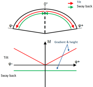
Simplified operating principle
For the angle ranges starting from 0°, a separate characteristic curve can be set for each direction.
This allows the characteristics of the sway and rollback to be set independently of each other.
This can be changed individually for each axle and depending on the driving condition.
In addition to a linear characteristic curve that simulates a spring characteristic curve, constant torques and any conceivable characteristic curve within the actuator’s operating range can also be set.
Operating range MR actuator ATD 1200
Operating range MR actuator ATD 1200 with gearbox
Concept comparison
2 Wings
Maximum possible swivel angle actuator 110°
Swivel blade torque 250 Nm
Translation ratio 4,75
Output locking torque 1200 Nm
Resulting swivel angle 23°
(Required) swivel angle 20°
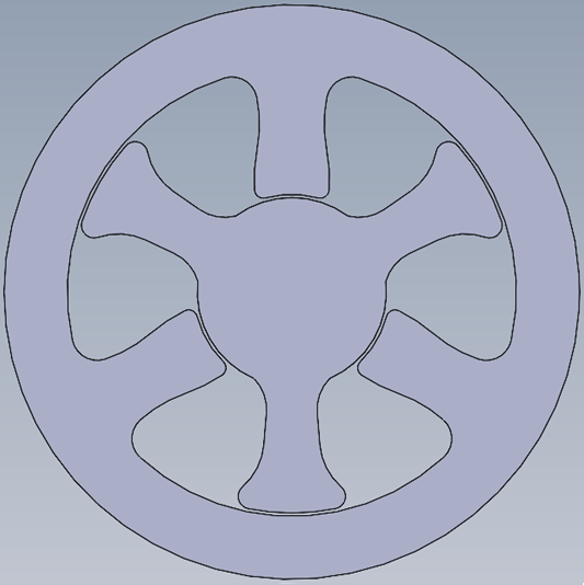
3 Wings
Maximum possible swivel angle actuator 60°
Swivel blade torque 375 Nm
Translation ratio 2,4
Output locking torque 900 Nm
Resulting swivel angle 25°
(Required) swivel angle 20°
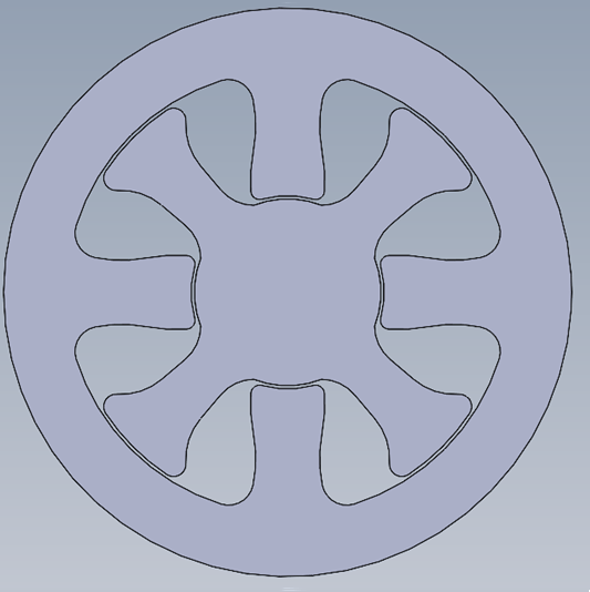
4 Wings
Maximum possible swivel angle actuator 30°
Swivel blade torque 500 Nm
Translation ratio 1
Output locking torque 500 Nm
Resulting swivel angle 30°
(Required) swivel angle 20°
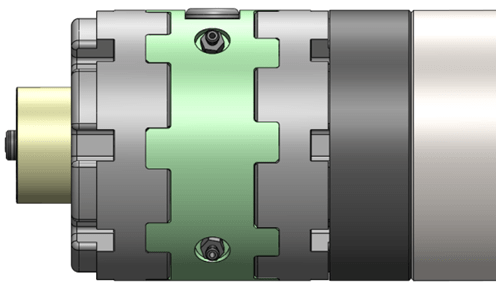
4 Wing system
Torque [Nm]: 500
Diameter [mm]: 91∅
Axial length [mm]: 113
Weight [kg]: 4,5 (prototype)
2 Wing system with gearbox i=2.4
Torque [Nm]: 600
Diameter [mm]: 91∅
Axial length [mm]: 160
Weight [kg]: 5,9 (prototype)
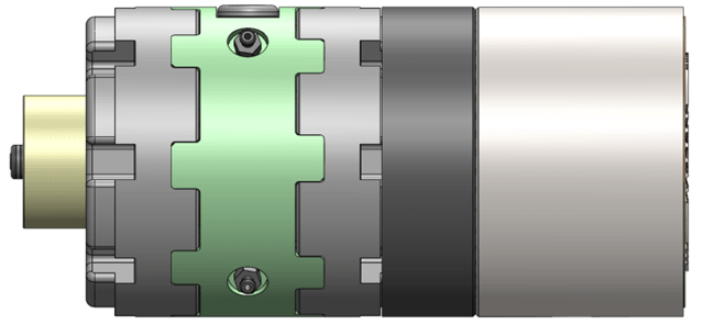
2 Wing system with gearbox i=4.75
Torque [Nm]: 1200
Diameter [mm]: 91∅
Axial length [mm]: 193
Weight [kg]: 7,3 (prototype)
The outer diameter of 91 mm is identical to the outer diameter of the active Schaeffler anti-roll bar. This means that the semi-active anti-roll bar always fits into the installation space of the Schaeffler anti-roll bar. If a larger diameter is possible in the vehicle, the torque increases.
Modular design
INVENTUS prefers the modular design, i.e. an MR-Device with 4 wings without gearbox, at least 30° swivel angle and 500 to 600 Nm maximum torque. Depending on the customer’s torque requirements, several identical units are interconnected.
Alternatively, two or more actuators can be coupled together to increase the maximum torque with the same diameter, e.g. front axle 2x 500 Nm (total 1000 Nm) actuator / rear axle 1x 500 Nm actuator).
This means that individual axles are not “over engineered”.
We use cookies on our website to give you the most relevant experience by remembering your preferences and repeat visits. By clicking “Accept”, you consent to the use of ALL the cookies.
This website uses cookies to improve your experience while you navigate through the website. Out of these, the cookies that are categorized as necessary are stored on your browser as they are essential for the working of basic functionalities of the website. We also use third-party cookies that help us analyze and understand how you use this website. These cookies will be stored in your browser only with your consent. You also have the option to opt-out of these cookies. But opting out of some of these cookies may affect your browsing experience.
Necessary cookies are absolutely essential for the website to function properly. These cookies ensure basic functionalities and security features of the website, anonymously.
Google Analytics (US provider)
Website tracking and optimisation with Google Analytics. (for cross-device recording of users)
Website tracking and optimisation with Google Analytics.